
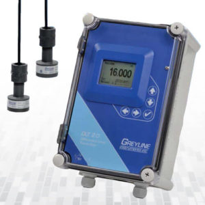
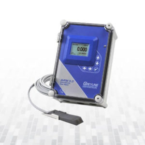
Open Channel Flow Monitor OCF 5.0
- Non-Contacting Ultrasonic Sensor
- Large, Backlit LCD Display
- 12-Digit Totalizer
- Reverse Flow Measurement
- Isolated 4-20mA (1000 ohm)
- 2 Programmable Control Relays
- Automatic Sensitivity Adjustment
- Built-in 5-Key Calibrator
- Optional 2 million point Data Logger with USB output to Flash memory
- Description
- Reviews (0)
- Specifications
- Brochure
- User’s Guide
- How It Works
Product Description
- Non-Contacting Ultrasonic Sensor
- Large, Backlit LCD Display
- 12-Digit Totalizer
- Reverse Flow Measurement
- Isolated 4-20mA (1000 ohm)
- 2 Programmable Control Relays
- Automatic Sensitivity Adjustment
- Built-in 5-Key Calibrator
- Optional 2 million point Data Logger with USB output to Flash memory
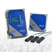
Continuously monitor, display, totalize and data log flow through any flume or weir. The OCF 5.0 includes a non-contacting ultrasonic sensor that mounts just 8″ (203.2 mm) above the flowing water. It is accurate (±0.25%) and reliable. There is no obstruction to flow and no fouling. Use the built-in Keypad/menu system to select your flume or weir from the Menu and to choose measurement units (gallons, liters etc.)
The Greyline OCF 5.0 includes built-in 2-million point Data Logger and flow reporting system. Connect a flash memory stick to the flowmeter’s USB output to download log files and then view your data in graph and table formats with ‘Greyline Logger’ software – supplied free with each OCF 5.0. Daily flow reports including minimum, maximum, average and total daily flow can be viewed directly on the backlit OCF 5.0 LCD display. New! Logger Download to USB Flash Drive
Use the isolated 4-20mA to transmit flow to remote chart recorders or displays, and the control relays are programmable for level/flow alarm, and flow proportionate pulse (for samplers, chlorinators or remote totalizers). An Intrinsic Safety Barrier is optional for sensor and cable installation in hazardous rated locations. The separate, watertight electronics/display enclosure is mounted at a convenient location within 500 ft (150 m) of the sensor.
Be the first to review “Open Channel Flow Monitor OCF 5.0”
OPEN CHANNEL FLOW MONITOR SPECIFICATIONS
SCOPE: This instrument shall provide for indicating, transmitting, totalizing and data logging of the flow rate through a flume, weir, or other primary measuring device.
A. GENERAL
- Open Channel Flow Monitor to consist of an non-contacting ultrasonic sensor, connecting cable, and a remote enclosure with indicating, transmitting and controlling electronics.
- Measurement accuracy shall be ±0.25% of Range or 2 mm (0.08"), whichever is greater, and shall be automatically temperature compensated.
- Sensor cable length shall be as required by installation, not to exceed 500' (152 m).
- System shall have no moving parts and shall not contact the water being measured.
- Shall include PC software program disk to determine open channel flow calibration values for non-standard flumes and weirs.
B. SENSING ELEMENT
- Sensor shall withstand accidental submersion to 10 ft (3 m) maximum.
- Sensor minimum range shall be 8" (203.2 mm) and maximum range shall be 15 ft (4.57 m).
- Sensor shall be constructed of PVC.
- Sensor operating temperature shall be from -40°F to 150°F (-40°C to 65°C).
- Sensor shall include integral temperature sensor. Temperature sensors requiring separate mounting and wire runs shall not be accepted.
C. SENSOR CONNECTING CABLE
- Provide RG62AU coaxial cable 25' (7.6m) continuous length, with waterproof, potted bond to the Sensor head.
- Extended sensor cable shall be RG62AU coaxial to a maximum of 500' (152m). Cable shall be spliced with screw terminal connections in manufacturer's recommended steel NEMA4 Junction Box.
- Level and temperature signals shall be conducted on one single coaxial cable. Separate or multiple-conductor cables shall not be accepted.
- Sensor cable shall be installed in grounded metal conduit.
D. TRANSMITTER
- The transmitter shall provide for field calibration to common primary metering devices, plus allow entry of "K" and "n" values for calibration to nonstandard flumes, weirs or open channels. Systems requiring calibration by Parameter codes, BCD switches or external calibrators shall not be accepted.
- Calibration data shall be password protected and permanently stored through power interruptions for a minimum of 12 months.
- Field calibration shall allow selection and automatic conversion of measurement units, measurement span, high/low flow alarm relay and flow proportional relay pulse rates.
- Transmitter shall permit field programmable damping to smooth output in turbulent flow conditions, and programmable rejection time to disregard false signals from rain, wind, floating objects and spurious echoes.
- Transmitter operating temperature shall be from -5° to 140°F (-20° to 60°C). Transmitter shall contain a thermostat-controlled enclosure heater for condensation protection below 30°F (-1°C).
- Transmitter shall have an isolated 4-20mA output rated for 1000 ohm maximum load with menu-selectable 0-5VDC alternative.
- Have a built-in 2 million point Data Logger with USB output to flash drive or mass storage device. Include Windows software for data log analysis, graphing and export.
- Provide two relay contacts rated 5 amp SPDT programmable for single set point alarms, dual set point pump control, pump alternation, temperature alarm, flow totalizer pulse and/or echo loss alarm.
- Provide a white, backlit matrix LCD display indicating flow rate, level, relay states and 16-digit totalizer in user-selected engineering units and with language selection including English, French and Spanish.
- Transmitter display indicating level or flow rate, units of calibration, totalizer and relay states shall be visible without opening cover.
- Transmitter shall be housed in a wall-mount, watertight NEMA4X (IP66) enclosure with hinged, clear cover. Mounting hardware shall be included.
- Transmitter electronics shall be surge protected on AC power input, sensor and 4-20mA/0-5V outputs.
- Transmitter power input shall be 100-240VAC 50-60Hz with power consumption of 4.0 Watts or less.
- The transmitter shall permit plug-in field installation and auto-detection of optional accessories including additional control relays.
E. OPTIONAL FEATURES FOR INSERTION AS REQUIRED
- Have power input of 9-32VDC and power consumption of less than 4.0 Watts.
- Sensor cable shall be 50 ft. (15 m) continuous length with potted bond to the Sensor head.
- Sensor cable shall be 100 ft. (30 m) continuous length with potted bond to the Sensor head.
- Separate length extended sensor coaxial cable shall be extended to a total maximum length of 500 ft (152m). Cable shall be spliced with screw terminal connections in manufacturers recommended steel NEMA4 Junction Box.
- Sensor, connecting cable and junction boxes shall be rated intrinsically safe to Class I,II,III, Div. I,II, Groups C,D,E,F,G.
- Have a thermostat controlled enclosure heater for Transmitter operation at temperatures below freezing.
- Have manufacturer's recommended enclosure sunscreen to permit Transmitter mounting in direct sunlight.
- Have manufacturer's recommended Sensor sunscreen to permit temperature-compensated Sensor mounting in direct sunlight.
- Have manufacturer's recommended Panel Mount Flange assembly for enclosure installation.
- Have 4 additional (6 total) control relays, rated 5 amp SPDT and programmable for single set point alarms, flow proportionate pulse, temperature alarm and/or echo loss alarm.
Specifications are subject to change without notice.
Please Contact AKTEK if you need more information or for advice in your application. We can provide quotations
OCF 5.0 Brochure
OCF 5.0 User Guide
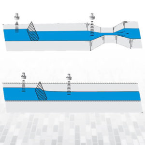
Open Channel Flow
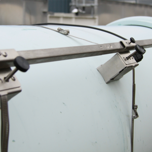
The common method of measuring flow through an open channel is to measure the height or HEAD of the liquid as it passes over an obstruction (a flume or weir) in the channel. Using ultrasonic level technology, Greyline open channel flow meters include a non-contacting sensor mounted above the flume or weir. By measuring the time from transmission of an ultrasonic pulse to receipt of an echo, the water level or "Head" is accurately measured.
Flumes and weirs are specially designed channel shapes that characterize the flow of water. Common types are Rectangular Weirs, V-Notch Weirs, Parshall flumes and Palmer Bowlus flumes. The choice of flume or weir type depends on the application: flow rate, channel shape and solids content of the water. Contact Greyline Instrumentsinfo@greyline.com for advice on selection of a suitable flume or weir for your application.
Our open channel flow meters can be calibrated to any flume or weir by menu selection. The open channel flow meter electronics use an internal formula to calculate flow rate (Flow = K Hn, where 'K' and 'n' are constants and 'H' is Head as measured by the instrument). Calibration to uncommon or custom flumes can be done by direct entry of 'K' and 'n' constants. Greyline also offers a PC software program "Find K&n" to develop calibration constants from a flume or weir flow chart.
Related Products
-
 Read moreQuick View
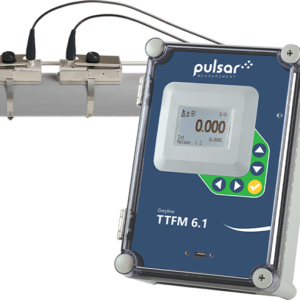
Transit Time Flow Meter, TTFM 1.0
- Non-Contacting Clamp-on Ultrasonic Transducers
- Works on Metal and Plastic Pipes
- Large Backlit Flow Rate Display and Totalizer
- Isolated 4-20mA Output
- Built-in 5-Key Calibrator
- 2 Programmable Control Relays
- Optional 2 Million Point Data Logger
Read moreQuick View -
 Read moreQuick View
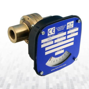
Mechanical Flow Meter Small Serie
Read moreQuick View -
 Read moreQuick View
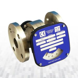
Mechanical Flow Meter Medium Serie
Switches: field adjustable, suitable for batching,
trending, totalising or recording where required.
0-10 v or 4-20mA output.Read moreQuick View -
 Read moreQuick View
Differential Level Transmitter DLT2.0
Measures Level, Differential Level and Open Channel Flow
Two Non-Contacting Ultrasonic Sensors
Large White Backlit LCD Display
Three Isolated 4-20mA Outputs
Built-in 5-Key Calibration
2 Programmable Control Relays
Optional 2 Million Point Data Logger
Optional Intrinsically Safe SensorsRead moreQuick View -
 Read moreQuick View
Mechanical Flow Meter Wafer Serie
Direct reading Flow Rate Indication
Optional (field adjustable) switch(es)
Optional Non-Contact 4-20mA Output
High Pressure available
Mounts in any orientation
No straight Pipe Run required • Connection sizes from 3” to 12”Read moreQuick View -
 Read moreQuick View
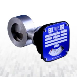
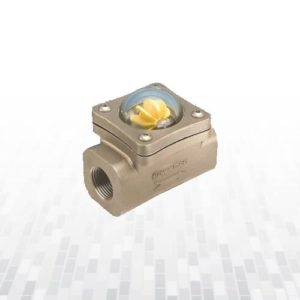
Flow Indicator Spinner
• Suitable for water and other clear liquids and gases
• 16 bar pressure and 200˚C temperature capability
• Precision moulded glass dome with yellow PPS plastic spinner
• Can be used in any orientation
• Bi-directional flow
• Operates over a wide flow rangeRead moreQuick View -
 Read moreQuick View
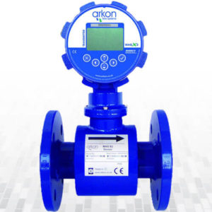
Electromagnetic Flow Meter MAGX2
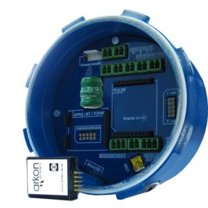
MAGX2 offers a wide range of modules to allow each customer to “design” their own solution for his application. The modules are “plug and play”, can be easily installed or removed from the mother board (always check first that the unit is powered off) and have in most of the cases the size of a big post stamp.
Arkon modules are divided in:
- Power supply modules.
- Output modules.
- Digital communication modules.
Read moreQuick View -
 Read moreQuick View
Mechanical Flow Meter Low Flow
-Water, De-Ionised Water
-Soluble Oils (Glycols)
-Petroleum Based Fluids
-Synthetic Based Fluids Coolants
-Corrosive Fluids Paints Solvents
-Air & GasesRead moreQuick View -
 Read moreQuick View
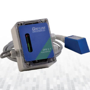
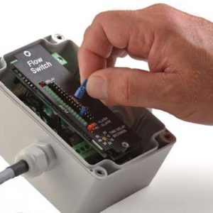
Doppler Flow Switch DFS 5.1
- Flow Control from the Outside of Metal or Plastic Pipes
- 5 amp DPDT Control Relay
- Adjustable ON/OFF Set-Points
- Hi or Lo Flow Alarm Mode
- Adjustable Time Delay
- Relay Status LED
- Flow Rate LED bargraph
Read moreQuick View -
 Read moreQuick View
Area-Velocity Flow Monitor AVFM 5.0
- For Open Channels and Pipes No Flume or Weir Required
- Ultrasonic – Measures Velocity + Level to Calculate Flow
- Works in partially filled and surcharged pipes
- 3 Isolated 4-20mA Outputs(Flow, Level and Velocity)
- Isolated 4-20mA/0-5V Output
- Totalizer and 2 Control Relays
- Optional Intrinsically Safe Sensor
Optional built-in 2-million point Data Logger
Read moreQuick View

Reviews
There are no reviews yet.